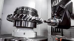
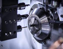
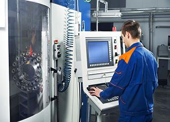
PARIS, France — From paper punch cards in post-war aviation labs to multi-axis automated hubs powering global aerospace, Computer Numerical Control (CNC) machining has evolved into a cornerstone of modern industrial manufacturing. Valued at tens of billions of dollars worldwide and projected to clear $100 billion as smart manufacturing accelerates, automated subtractive manufacturing allows factories to transform digital CAD models into micro-precision components without direct human intervention. Driven by advances in computer-aided design (CAD), computer-aided manufacturing (CAM), and Industrial Internet of Things (IIoT) platforms, CNC tools now define the boundaries of mass production across sectors ranging from biomedical devices to defense.
Core Operational Principles and Process Workflow
Unlike additive manufacturing techniques like 3D printing, CNC machining uses subtractive processes—removing material from a solid workpiece using high-speed rotary tools or electrical discharges until the exact specifications are met.
The standardized industrial workflow follows four critical stages:
CAD Model Generation: Designing 2D vector or 3D solid models using specialized software, subsequently exported into universally compatible formats like STEP or IGES.
File Conversion to Machine Code: Processing the spatial design through CAM software to extract component geometry and generate G-code instructions that govern feed rates, spindle speed, and tool paths.
Machine Calibration: Securing raw materials (billets) into workholders, vices, or chucks, while installing specific tooling bits such as end mills, drills, or taps.
Program Execution: Running the computerized code to guide multi-axis toolheads through cutting, turning, or drilling operations with micrometer-level precision.
Primary Machining Operations & Material Compatibility
Machining Operation
Mechanism
Primary Applications
Material Options
CNC Milling
Moves rotating cutting tools against stationary workpieces across multiple axes
Face milling, deep cavities, complex structural enclosures
What does this decision/news mean for the citizen/follower?
For consumers and daily tech users, the ubiquity of CNC machining directly underpins the durability, miniaturization, and accessibility of everyday devices. Modern unibody aluminum laptops—pioneered by Apple’s single-block CNC milling techniques—as well as high-density circuit boards inside smartphones owe their structural integrity and compact form factor to computer-guided machining.
For the average citizen, advancements in CNC production reduce end-user costs for critical goods, improve automotive safety standards through precision-milled braking components, and enable life-saving medical innovations. Custom orthopedic prosthetics, titanium joint implants, and non-invasive surgical robotics are all made economically viable through automated, low-volume CNC runs.
Historical Evolution: From Punch Cards to Smart Factories
The roots of computerized manufacturing trace back to the late 1940s, when John T. Parsons partnered with MIT’s Servomechanisms Laboratory to fabricate complex helicopter rotor blade templates using paper punch cards. By 1952, Parsons and MIT demonstrated the first experimental continuous-path numerical control (NC) milling machine, establishing the baseline for automated toolpaths.
Subsequent milestones fundamentally altered the economic landscape of production:
The APT Language (1950s): Lead researcher Douglas T. Ross developed the Automatically Programmed Tool (APT) language, creating a standardized programming framework that became the global standard by 1978.
PRONTO & Direct Numerical Control (1957–1960s): Dr. Patrick Hanratty introduced PRONTO, launching CAM software, while Direct Numerical Control (DNC) eliminated paper tapes by feeding files straight from computers to tool controllers.
PC Democratization & 3D Integration (1970s–1980s): The advent of low-cost minicomputers, Unix workstations, and 3D CAD/CAM in 1976 enabled real-time multi-tasking across multi-axis lathes and milling centers.
Looking Ahead
As industrial hubs across the Asia-Pacific, Europe, and North America adopt Industry 4.0 frameworks, CNC machining is converging with machine learning and automated robotics. Software platforms like FANUC’s FIELD now connect CNC tools directly to cloud networks, providing predictive maintenance alerts and real-time operational diagnostics to eliminate factory downtime. Moving forward, the fusion of sustainable manufacturing—focused on lower carbon footprints and minimal material waste—with multi-axis hybrid CNC systems will ensure that computerized machining remains the central engine of global hardware innovation.
Securing a role as a high-precision CNC machinist requires far more than merely stating you know how to operate heavy equipment. Candidates must master a structured approach—beginning with a punchy 60-second elevator pitch that outlines core multi-axis experience, tight-tolerance capabilities, and process optimization. Success on the interview floor relies heavily on organizing technical competencies across machine controls, workholding, manual G-code editing, quality inspection, and material science, while leveraging specific action verbs and methodical problem-solving workflows.
What does this decision/news mean for the citizen/follower?
For technical professionals and job seekers navigating modern manufacturing environments, upgrading how you communicate your shop-floor value is critical. Modern engineering shops face tighter margins and higher expectations for zero-defect output, meaning hiring managers are moving away from vague summaries and searching for candidates who can articulate exact troubleshooting steps.
Clear Communication: Translating raw machining habits into structured, repeatable interview frameworks builds immediate trust with technical evaluators.
Problem-Solving Transparency: Demonstrating precise methods for handling tool chatter, dimensional drift, and emergency recoveries shows you can protect expensive equipment and tight schedules.
Competitive Edge: Setting yourself apart from general operators by showing deep familiarity with controls, geometric dimensioning and tolerancing (GD&T), and offsets.
Echoes from the Machine Shop: A Historical Perspective
The evolution of the CNC interview process reflects a broader transformation within manufacturing over the last few decades. Historically, hiring heavily emphasized pure mechanical tenure and raw hours spent standing in front of a specific lathe. Today, as digital integration, advanced CAM packages, and strict quality control standards take center stage, the industry demands articulate technicians who can combine old-school craftsmanship with systematic data-driven troubleshooting.
Looking Ahead
As advanced automation and complex multi-axis milling continue to redefine modern manufacturing corridors, the ability to clearly demonstrate technical competence during an interview will remain a core career asset. Candidates who treat the interview as an extension of professional quality control—structured, methodical, and evidence-based—will consistently land the most rewarding roles in the industry.
Are you ready to update your technical pitch for your next career move, or what has been your toughest hurdle during a machine shop technical evaluation?
This video provides comprehensive walkthroughs of common technical questions, tool selection, and programming standards to help you prepare effectively for your upcoming interview.
1. Structure Your Self-Introduction (The 60-Second Elevator Pitch)
Use a concise three-part formula: Who You Are $\rightarrow$ Core Expertise $\rightarrow$ Value You Bring.
Example Introduction:“I am a qualified CNC Machinist with over [X] years of experience operating 3-axis and 5-axis CNC mills and lathes in high-precision industrial environments. My background centers on full-cycle machining—from interpreting engineering drawings and setting up workholding to G-code editing, manual tool setting, and holding tight tolerances down to $\pm0.0005”$. In my previous roles, I focused on reducing setup times, optimizing speeds and feeds for tough alloys, and ensuring zero-defect quality control. I’m looking to bring my setup, machining, and troubleshooting experience to your team.”
2. Presenting Your Technical Skills Framework
Organize your technical competencies into clear functional categories when discussing your capabilities:
Competency Area
Key Technical Details to Mention
Machine Operation & Control
Fanuc, Haas, Siemens, or Heidenhain controls; 3-axis/4-axis milling, CNC turning, live tooling.
Calculating SFM, RPM, and chip load for aluminum, stainless steel (304/316), titanium, and tool steels; selecting proper insert grades and coatings.
3. Explaining Technical Skills with Action Verbs
When interviewers ask, “How do you approach [Task]?”, use specific, concrete steps rather than vague summaries:
Instead of:“I know how to set up machines and run parts.”
Say:“I clean and align all workholding using a dial indicator to ensure zero runout, probe or edge-find X/Y datums for G54, set Z offsets with a optical tool setter, and execute a single-block dry run with rapid override at 5% to verify tool clearances.”
4. Demonstrating Shop-Floor Problem Solving
Highlight your ability to diagnose and fix machining issues independently:
Chatter & Surface Finish: Explain how you evaluate rigidity, reduce tool stickout, adjust feed per tooth, or shift spindle speeds to break harmonic vibration.
Dimensional Drift: Explain how you use controller wear offsets (e.g., adjusting G41 wear values) rather than altering CAM code for minor tolerance adjustments.
Tool Failure: Detail your process for feed hold/E-stop recovery, clearing broken carbide debris, inspecting holders/spindles, and re-establishing Z-offsets before executing a safe line-restart.
1. How do you set up a Work Coordinate System (WCS) like G54 on a CNC machine?
Sample Answer: “I clean the table, fixture, and stock to ensure no chips affect positioning. I use a touch probe or edge finder to locate the X and Y datum edges of the stock, accounting for the edge finder radius if using a manual one. For the Z-axis, I establish the zero point—either top of stock or top of table—using a tool setter or precision block. I input these relative coordinates into the G54 register on the control panel, then perform a dry run or single-block air-cut to verify the program home relative to the part.”
2. What is the difference between G00 and G01, and why is the distinction critical?
Sample Answer: “G00 is rapid linear motion used strictly for positioning the tool in non-cutting space at maximum machine speed. G01 is linear interpolation, which moves the tool at a specified feed rate (F) to execute an active cut. mistaking a G00 for a G01 inside stock will cause a tool crash or damage the workpiece because the tool moves at full speed without cutting physics accounted for.”
3. How do you calculate Spindle Speed (RPM) and Feed Rate for a milling or turning operation?
Sample Answer: “I start with the recommended Surface Feet per Minute (SFM) for the material and tool combination. For RPM, I use $\text{RPM} = (\text{SFM} \times 3.82) / \text{Tool Diameter}$. Once I have RPM, I calculate Feed Rate using $\text{Feed Rate (IPM)} = \text{RPM} \times \text{Number of Flutes} \times \text{Chip Load per Tooth}$. If I notice chatter or heat buildup during the cut, I dial back RPM or adjust the feed per tooth accordingly.”
4. How do cutter radius compensation (G41/G42) and length compensation (G43) work?
Sample Answer: “G41 offsets the tool to the left of the programmed path, and G42 offsets it to the right, allowing the control to adjust for tool diameter wear without rewriting the program. G43 calls up tool length compensation relative to a specific offset register (e.g., H01), telling the Z-axis how long the tool extends from the spindle gauge line.”
5. How do you approach reading complex engineering drawings with GD&T callouts?
Sample Answer: “I review the title block for material, general tolerances, and projection type. I identify the primary, secondary, and tertiary datums establishing the reference frame. Then, I cross-reference GD&T callouts—like true position, runout, or parallelism—against my machining sequence to ensure key features are machined in the correct orientation or same setup where possible to avoid cumulative stack-up errors.”
6. What steps do you take when a tool breaks during a run?
Sample Answer: “First, I hit Feed Hold or Emergency Stop depending on the severity. I jog the Z-axis clear, inspect the workpiece for damage, and recover all broken carbide pieces from the cut zone. I inspect the tool holder and spindle for damage, replace the insert or tool, re-measure the tool offset using the tool setter, reload the code to a safe lead-in position or line number before the break, and restart with reduced feed to clear any work-hardened material.”
7. How do you prevent and fix chatter during a heavy cutting pass?
Sample Answer: “Chatter comes from a lack of rigidity or resonant vibration. To fix it, I first reduce stickout length on the tool or workholding. If the setup is fixed, I alter cutting parameters: slightly dropping the RPM or increasing feed per tooth to change the harmonic frequency and force the tool into a stable cut. I also check insert wear, depth of cut (DOC), or switch to an variable-flute end mill if necessary.”
8. What key daily preventive maintenance tasks do you perform on CNC machinery?
Sample Answer: “At start-of-shift, I check way lube levels, pneumatic pressure gauges, and coolant concentration using a refractometer. I wipe down spindle tapers and tool holders to keep them free of debris, empty chip trays, and verify that way covers move freely without chip buildup. At end-of-shift, I blow out the enclosure, clear swarf from the bed, and leave the machine in a clean, safe state.”
9. How do you handle inspecting a part with tight tolerances (e.g., ±0.0005″)?
Sample Answer: “I allow the part to stabilize to ambient shop temperature if it got hot during machining. I calibrate and use precision instruments like micrometers, bore gauges, or a CMM rather than standard calipers. I measure the part while still fixture-bound if possible; if re-machining is needed, I apply offset adjustments in the control wear table rather than editing the base code.”
10. How do M00, M01, and M30 differ in a program?
Sample Answer: “M00 is an unconditional program stop—the machine pauses execution until the operator presses cycle start (used for chip clearing or inserting hardware). M01 is an optional stop that only pauses the machine if the ‘Optional Stop’ button on the control panel is toggled on. M30 marks the end of the main program, stopping spindle and coolant, and rewinding the program back to the top.”